How to Choose the Right Irrigation Parts?
Choosing the right Irrigation Parts is not about buying the largest pump. It is about matching each component to water quality, crop needs, soil, and operating pressure. A mismatch can clog emitters, waste water, or leave the far end of a field dry. Small details matter.
USDA NASS’s 2022 Census of Agriculture recorded irrigation on 55.9 million acres across 212,714 farms. That national scale reflects how consequential reliable equipment selection can be for producers. FAO’s AQUASTAT database estimates that agriculture accounts for about 70% of global freshwater withdrawals. Regional conditions differ, however; a global statistic cannot determine one farm’s flow rate or layout. Measurements must do that.
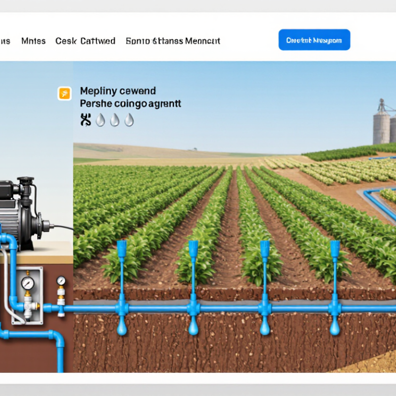
Start with a site check: source flow, pump pressure, elevation changes, filtration needs, and crop schedule. Then compare pipe diameter, valves, filters, emitters, fittings, and pressure regulators as one connected system. For example, fine sediment may demand filtration before drip emitters, while long rows may need pressure compensation. Manufacturer flow charts and pressure ranges are useful, but verify them against measured field conditions. Do not guess. A small fitting mismatch is easy to overlook; it deserves a second check. That pause can help prevent leaks, uneven watering, and avoidable replacement costs. Good choices are specific, documented, and maintainable—not merely inexpensive.
Assess Water Supply First: Measure Peak Flow, Pressure, and Total Dynamic Head
Before choosing irrigation parts, measure what the water source can actually deliver. Run the tap or pump under realistic operating conditions, then use a flow meter or a timed container test to estimate peak flow. Check the flow while other expected outlets are running; a quiet test can overstate available supply. Record each reading. Small differences matter.
Measure pressure with a gauge at the supply point, both with no water flowing and while the system runs. The second reading shows working pressure, which can drop when flow increases. Then estimate total dynamic head (TDH): include elevation lift, pressure needed at the emitters, and losses through pipe, filters, valves, and fittings. A long, narrow pipe can lose more pressure than expected. The calculation is useful, but field readings are rarely perfect, so recheck after installation.
Tips: Test during the busiest likely watering period. Note the gauge location, flow rate, and elevation change. If pressure fluctuates, repeat the test on another day. Use these measurements to match pipe diameter, filtration, valves, and emitters to the actual supply—not a guessed capacity.
Compare Delivery Methods: Drip Runs at 90–95% Efficiency; Sprinklers at 75–85%
How to Choose the Right Irrigation Parts?
Drip irrigation commonly delivers water with about 90–95% efficiency, while sprinklers often range from 75–85%. These figures are useful comparisons, not guarantees. Actual performance depends on system design, water pressure, soil, and maintenance.
Drip lines place water near plant roots, reducing losses from wind and exposed wet surfaces. This can suit vegetable beds, shrubs, and rows where plants are spaced clearly. Check filters and emitters regularly; a small blockage can leave one plant dry while its neighbor gets plenty. Look closely.
Sprinklers cover wider areas and can be practical for lawns or closely planted crops. But wind may carry droplets away, and watering too quickly can send water across compacted soil. Use matched nozzles, check spray overlap, and water during calmer hours when possible. I have seen neatly arranged heads still leave dry strips, so a brief catch-can test can reveal uneven coverage. The higher efficiency figure for drip does not make it right for every site: installation cost, crop layout, and the time available for upkeep also matter.
Select Filtration to Suit Emitters: 120-Mesh Screens Are Common in Drip Systems
Choosing irrigation parts means matching filtration to the smallest emitter passage, not just the pipe size. A 120-mesh screen is common in drip systems, but it is not a universal setting. ASTM E11 gives a No. 120 test sieve an opening of 125 micrometres; irrigation-screen apertures can differ because wire thickness matters. Check the filter’s stated micron rating and the emitter specification before buying. Check the spec.
FAO’s Irrigation and Drainage Paper 29, Water Quality for Agriculture, identifies suspended particles as a clogging risk in microirrigation. Fine sand, algae, and organic debris can accumulate at emitter inlets, even when the water looks clear in a bucket. I treat 120 mesh as a starting point, not a magic setting. A filter that is too coarse may let particles through; one that is unnecessarily fine can increase pressure loss and cleaning frequency. Measure pressure before and after the filter, inspect the screen after a few operating cycles, and adjust if sediment builds up. Real water sources vary. Mesh numbers alone do not tell the whole story.
How to Choose the Right Irrigation Filter
Typical screen-filter openings by mesh count
A 120-mesh screen has a typical opening of about 125 microns and is commonly used in drip systems. Higher mesh counts have smaller openings. Actual openings vary with screen construction, so follow the filtration requirements specified for your emitters.
Size Pipes and Valves: Keep Water Velocity at or Below 5 ft/s
When choosing irrigation pipes, size them for the flow each zone actually needs, not just the pump’s maximum rating. A useful design target is to keep water velocity at or below 5 feet per second. Faster flow can increase friction loss, noise, and pressure surges when valves close. It may work. But it leaves less room for error.
Check the pipe’s true inside diameter; nominal size alone can mislead. For a quick estimate, flow in gallons per minute is about 12.24 times the inside diameter in inches squared at 5 feet per second. A pipe with a 1-inch inside diameter therefore carries roughly 12 gallons per minute at that velocity. Actual flow changes with pipe material, fittings, and operating conditions, so verify calculations against reliable sizing tables. Measure the zone flow if you can. It is easy to overlook a small difference.
Size valves for the required flow and acceptable pressure loss, not merely to match the pipe connection. A valve’s internal passage may be narrower than its inlet, creating a restriction. Check the manufacturer’s flow and pressure-loss data, then consider the full route, including elbows, filters, and elevation changes. A simple velocity check is valuable, though it cannot predict every pressure surge. If readings are close to the limit, recheck the assumptions before installation.